Overview
For the facility model, VISAC
utilizes the standard geometry package BRL-CAD. This package was chosen
for its compatibility with many other codes [e.g., EVA-3D, MEVA, PATRAN,
ADINA, EPIC-2, PSARC, and NASTRAN (U.S. Army, 1991)]. A full description
of the many uses of BRL-CAD can be found on ARL's BRL-CAD web site
http://ftp.arl.army.mil/brlcad/. However, unlike many CAD packages,
BRL-CAD uses solid geometry; therefore, it is almost impossible to
convert models from typical geometry packages that use surface
orientation to BRL-CAD. All BRL-CAD model generation typically must be
performed using the primitive graphical user interface MGED provided
with the BRL-CAD package (U.S. Army, 1991). MGED is a GUI intended to
provide a means of viewing the model and adding or modifying geometric
bodies within it; nonetheless, its editing capabilities are less than
desirable.
Because of the editing limitations found within MGED, a high-level
geometry editing package has been developed within VISAC. The purpose of
this editor is to provide a means of constructing a nuclear facility
from basic building blocks within a few minutes instead of the days or
weeks that it would normally take by using MGED.
Edificio Examples
This timesaving can be accomplished by assuming that most nuclear
facilities are constructed of the same basic building types. For the
construction of a simple Pressurized Water Reactor (PWR), several
buildings would be chosen from a menu. Typically, the buildings that
would be chosen are -- a containment building (that houses the reactor),
an auxiliary building (that houses the support equipment), a turbine
building (that houses the power production equipment), a diesel
generator building (to provide backup power, sometimes located within
the turbine building), a transformer building (can also be located
within the turbine building), and an intake structure (to provide
cooling water for the turbines). An example of this selection process is
provided in Figure 1. Not shown in the figure is the ability to rotate
the entire building and to show the internal structures (x-ray view).
These features will be revealed in Figure 2.
 |
|
Figure 1. Building a simple nuclear facility from menu boxes.
|
 |
|
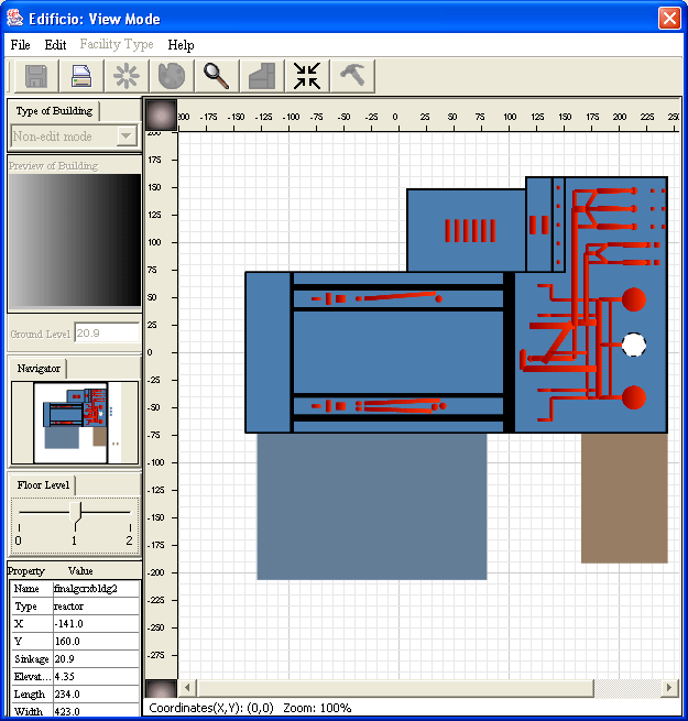
Figure 2. Components on the third floor of auxiliary building.
|
It is interesting to note that all of the containment buildings shown
look similar; however, each represents a significantly different design
(e.g., one represents a small ice condenser unit while another
represents a large dry containment). Also, separate containment
buildings are provided for the three major U.S. vendors: Westinghouse,
Babcock & Wilcox, and Combustion Engineering.
Once a facility is constructed, several modifications can be performed
to make the facility match the specific site of interest. These
adaptations include moving, adding, and rotating components within the
buildings. Components can also be exchanged amongst the various
buildings. Figure 2 shows a containment and auxiliary building. The
components on the third floor of the auxiliary building are shown in
red. As can be seen, the auxiliary building has been rotated 90 degrees from
what is visible in Figure 1. Each red component is intended to represent
a piece of equipment that will be used in the fault trees. The red
circles at the top of the auxiliary building, which correspond to
emergency water storage tanks, are required if the intake structure
becomes unavailable.
Figure 3 illustrates movement of these tanks along with several pumps
(the boxes shifted from the bottom of the building to the top). The
figure also demonstrates the addition of several components that
represent control consoles, indicated by the black arrow. Lastly, Figure
3 illustrates the addition of a grid that can be used to aid the user in
the proper placement of buildings.
 |
|
Figure 3. Movement of water storage tank and
creation of new components.
|
Example Edificio Windows
BRL-CAD geometry editor.
 |
|
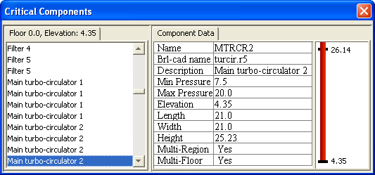
Figure 4. Screen shot showing a highlighted critical component.
|
 |
|
Figure 5. Component window with selected critical component
highlighted.
Note that this component is a multi-region and multi-floor component. The elevation
bar to the right indicates that this component goes through the ceiling and continues
on to the next floor above this one. |
Contact Information
Return to the VISAC home page